
Engineering the wake: hybrid flow control on a bluff body.
Our research division studies premature flow separation at low speeds — the same physics that governs stall margin, wake drag, and structural fatigue on every airframe we build. This is our own computational study, run in-house, on a hybrid passive and active flow-control strategy for a D-shaped bluff body.
- Reynolds Number
- 30,000
- Peak Drag Reduction
- 67.49%
- Base Pressure Recovery
- 72.3%
- Jet Actuation Freq.
- 13 Hz
Numerical Investigation of the Aerodynamics of a D-Shaped Bluff Body with Passive and Active Flow Control
An in-house computational study by the Tensorflux engineering team.
Summary
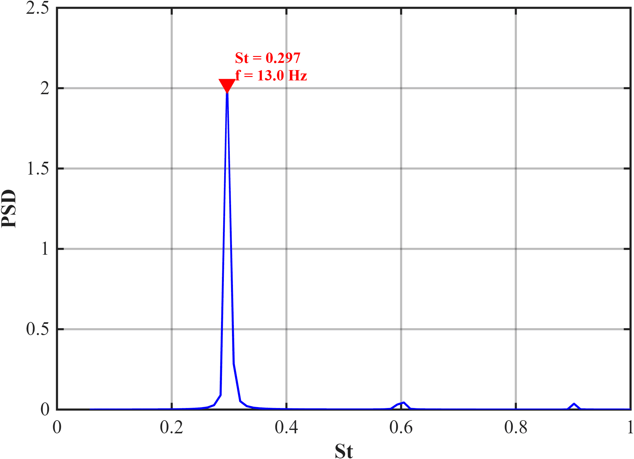
This study investigates a hybrid flow control method using both active and passive flow control over a D-shaped bluff body at a Reynolds number of 30,000. Baseline simulations reveal a significant pressure drag caused by the sharp, blunt corners, which promote flow separation. Addition of trailing-edge flaps demonstrates significant drag reduction — up to a 15° angle — by a staggering 65%. Upon further increase in the angle, the drag increases due to premature flow separation. Beyond this passive configuration, active flow control is then introduced via Zero Net Mass Flux (ZNMF) synthetic jets, actuated with a 90° phase shift at a dominant frequency of 13 Hz obtained from PSD analysis, and angled slightly parallel to the separated flow. Results show a drag reduction with an increase in the momentum coefficient. Analysis of the pressure at the rear end reveals substantial pressure recovery for the flow-control cases and a more uniform pressure distribution, confirming the drag-reduction phenomenon.
A domain sized to disappear, and a mesh proven independent.
The computational domain extends 32.76h downstream and 11h across the flow so outer boundaries never influence the wake. Prism inflation layers hold the wall-normal resolution to y⁺ < 1 along the body surface.
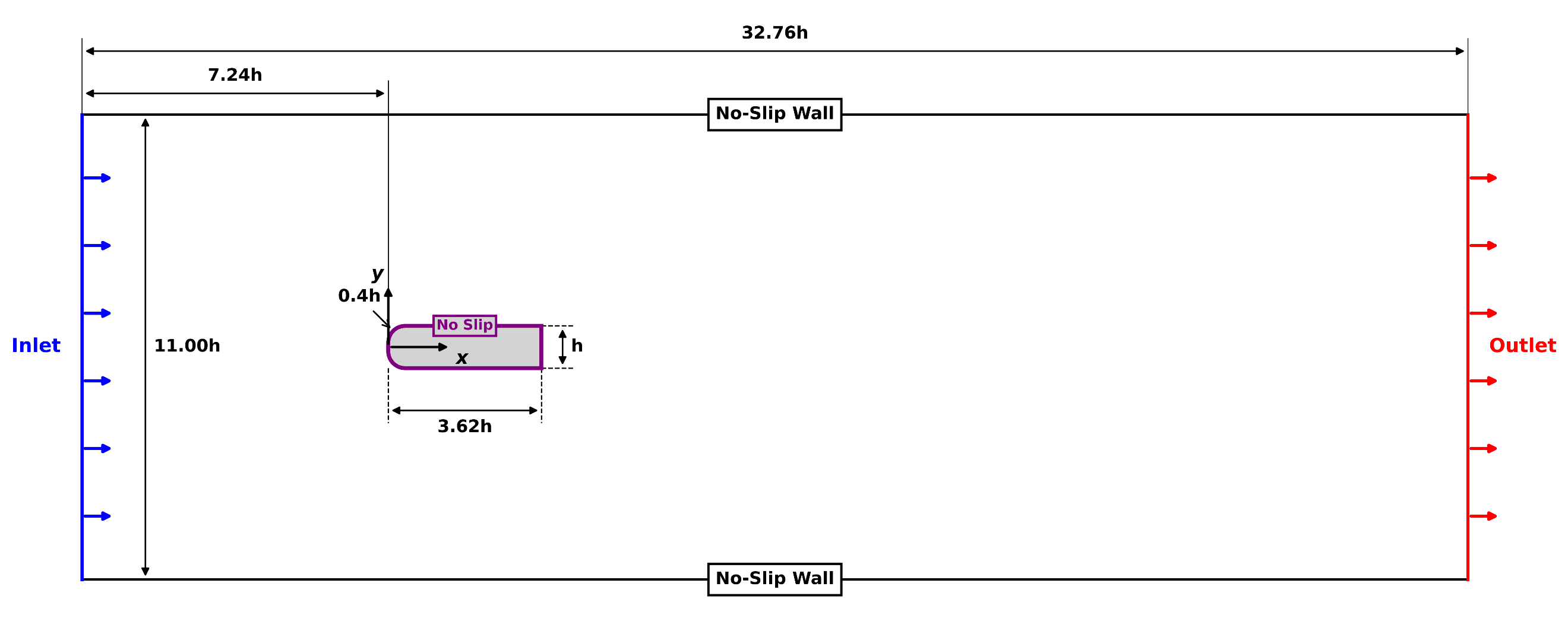
Fig. 1 — Domain & boundary conditions
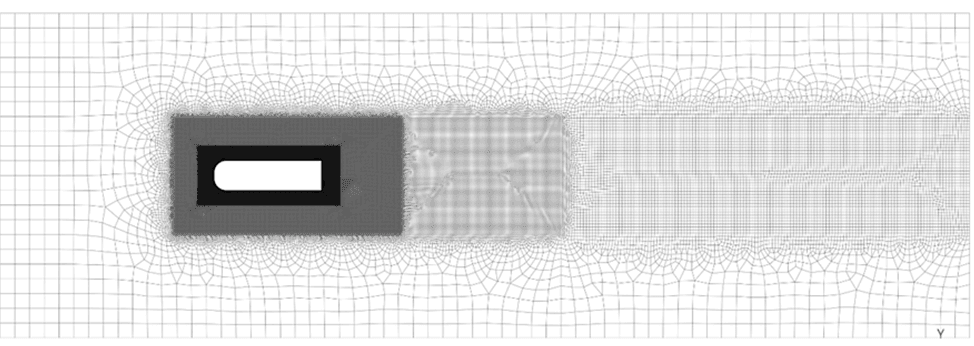
Fig. 2 — Local mesh refinement
Solver Configuration
- Solver
- ANSYS Fluent, URANS
- Viscous Model
- k-ω SST
- Fluid
- Air, ρ = 1.225 kg/m³
- Viscosity
- 1.789 × 10⁻⁵ kg/m·s
- Characteristic Length (h)
- 100 mm
- Time Step
- 0.001 s
- Reynolds Number
- 30,000
Independence & Validation
Four mesh densities were tested from 90,000 to 400,000 elements. The 250,000-element mesh was selected: refining further to 400,000 elements changed the mean drag coefficient by just 0.07%.
Baseline results were validated against Gilka et al. (2010) under matched conditions. The dominant vortex-shedding Strouhal number matched to within 1.1% (0.263 vs. the reference 0.2659), confirming the solver correctly captures the unsteady wake dynamics.
A 15° trailing-edge flap cuts drag by 65%.
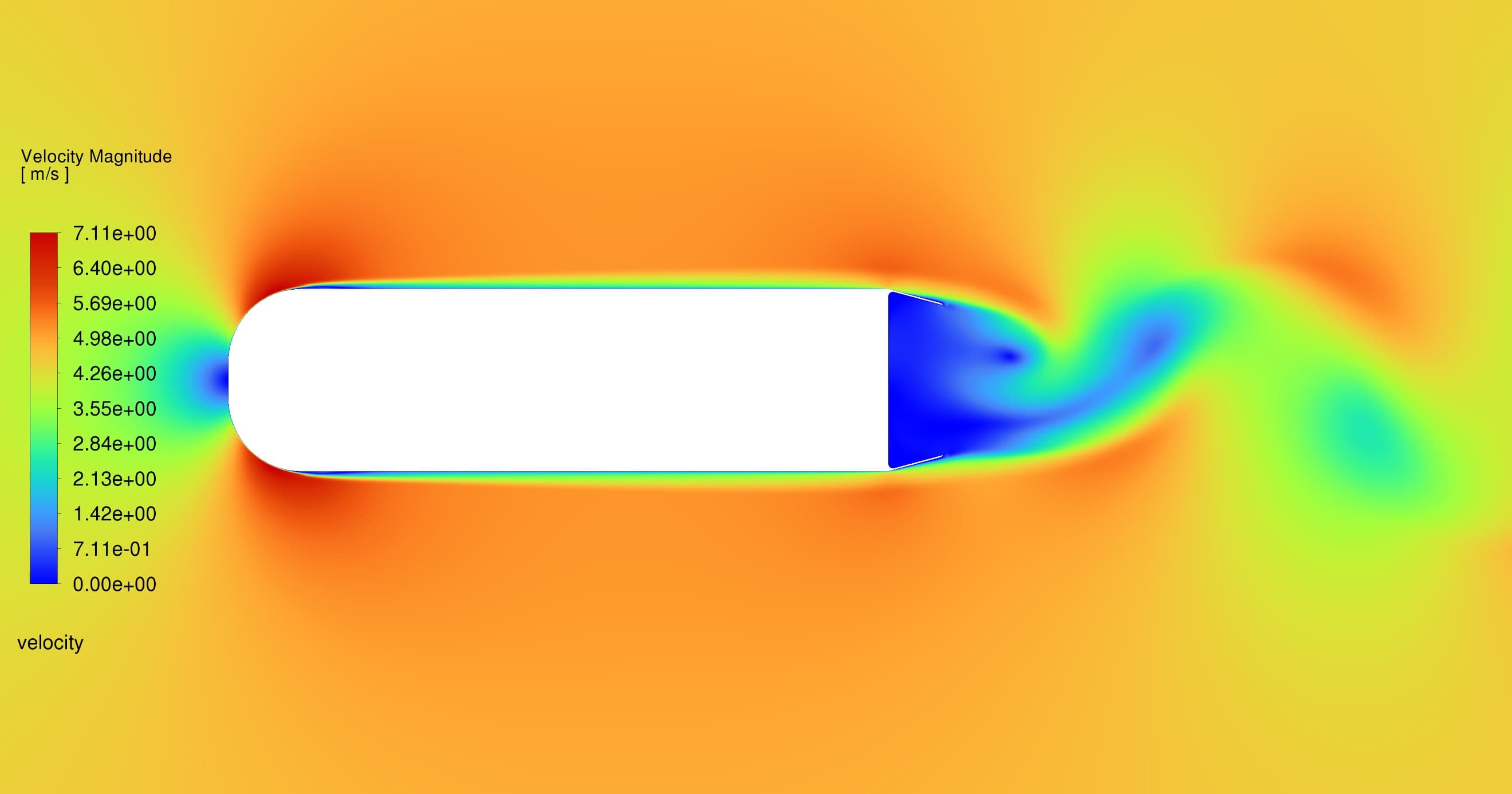
Baseline velocity contour · Kármán wake
Without control, the flow separates immediately at the sharp trailing corners of the baseline body, rolling into the wide, highly turbulent wake shown here — a von Kármán vortex street. The pressure differential this creates between the front stagnation point and the low-pressure wake accounts for most of the aerodynamic drag.
Thin splitter flaps attached to both trailing corners vector the separated shear layers inward, narrowing the wake and delaying vortex roll-up. Sweeping the flap deflection angle found a clear optimum: performance improves up to 15°, then reverses as the flow separates prematurely off the flap itself under an adverse pressure gradient.
1.297 → 0.448
mean C_D, baseline → 15° flap
80.71%
RMS lift-fluctuation reduction
Synthetic jets, tuned to the wake's own frequency.
A Zero Net Mass Flux (ZNMF) synthetic jet was added at each flap, positioned at 3.67h — just beyond the 3.5h flow-separation point. Rather than blowing normal to the surface, the jets are angled parallel to the separated flow and fired with a 90° phase shift between the top and bottom pair, disrupting the natural vortex shedding and sweeping the wake downstream.
PSD analysis — dominant frequency locked at 13 Hz
C_D / C_D0 vs. momentum coefficient (C_μ)
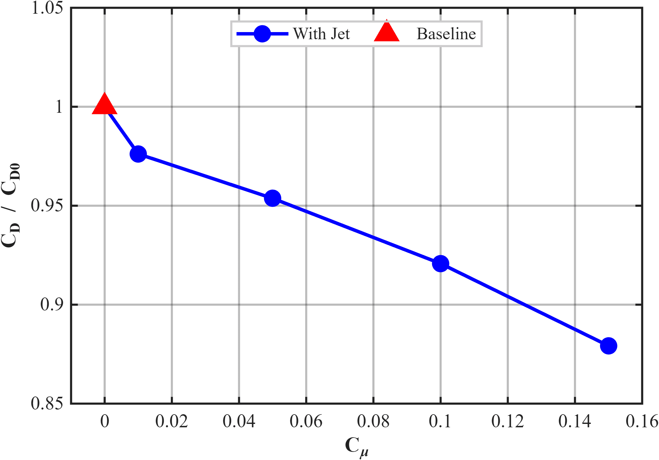
Four momentum coefficients were tested — 0.01, 0.05, 0.10, and 0.15. Drag kept falling as momentum coefficient rose, but a value above 0.10 is generally considered high-intensity control, and the electrical cost of driving the actuator starts to outweigh the aerodynamic gain. A momentum coefficient of 0.05 was chosen as the practical optimum.
67.49%
total drag reduction
76.13%
RMS lift reduction
72.3%
base pressure recovery
90°
jet phase shift
Three configurations, measured against the same clock.
C_L vs. t* — baseline, flap, flap + jet
C_D vs. t* — baseline, flap, flap + jet
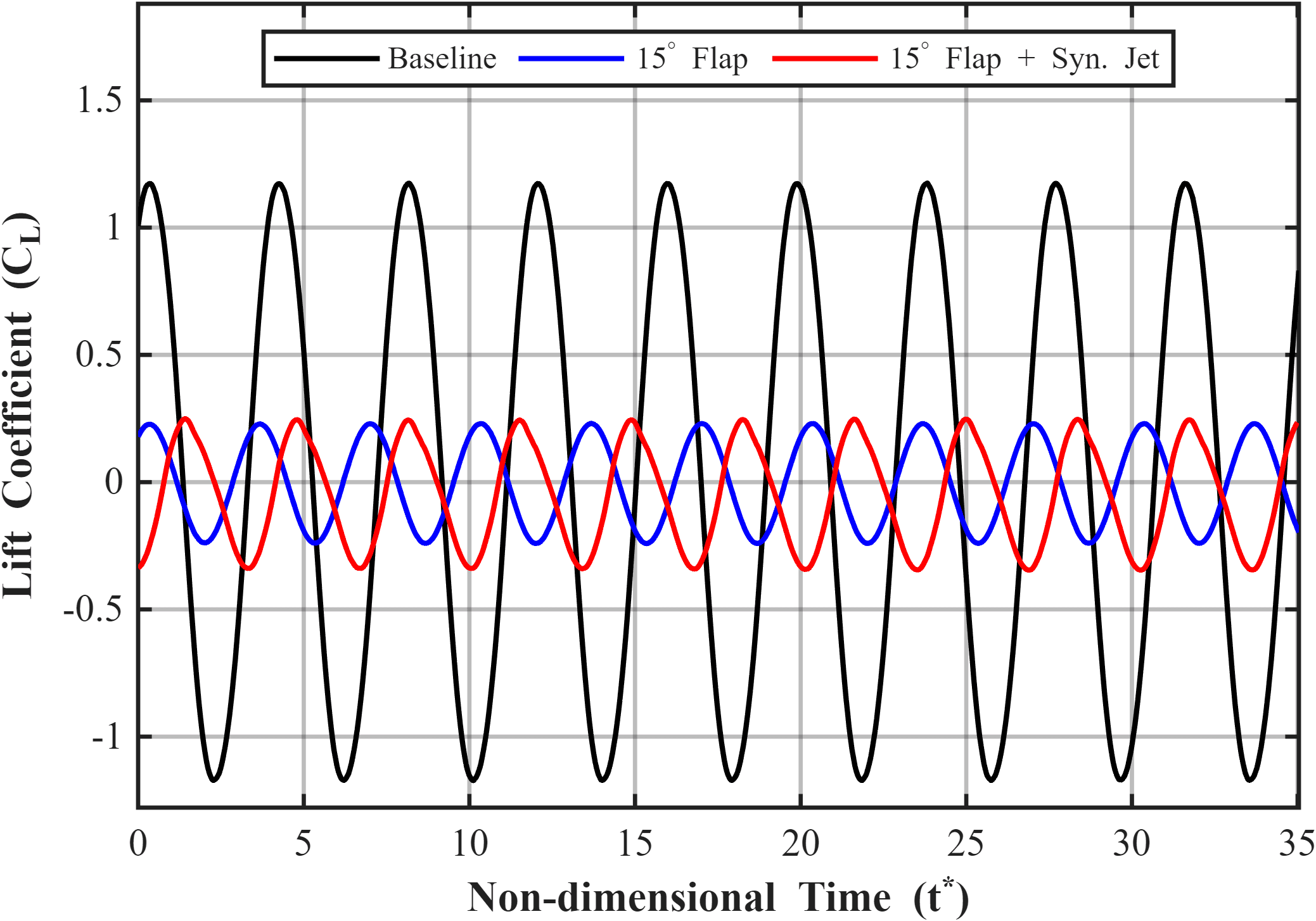
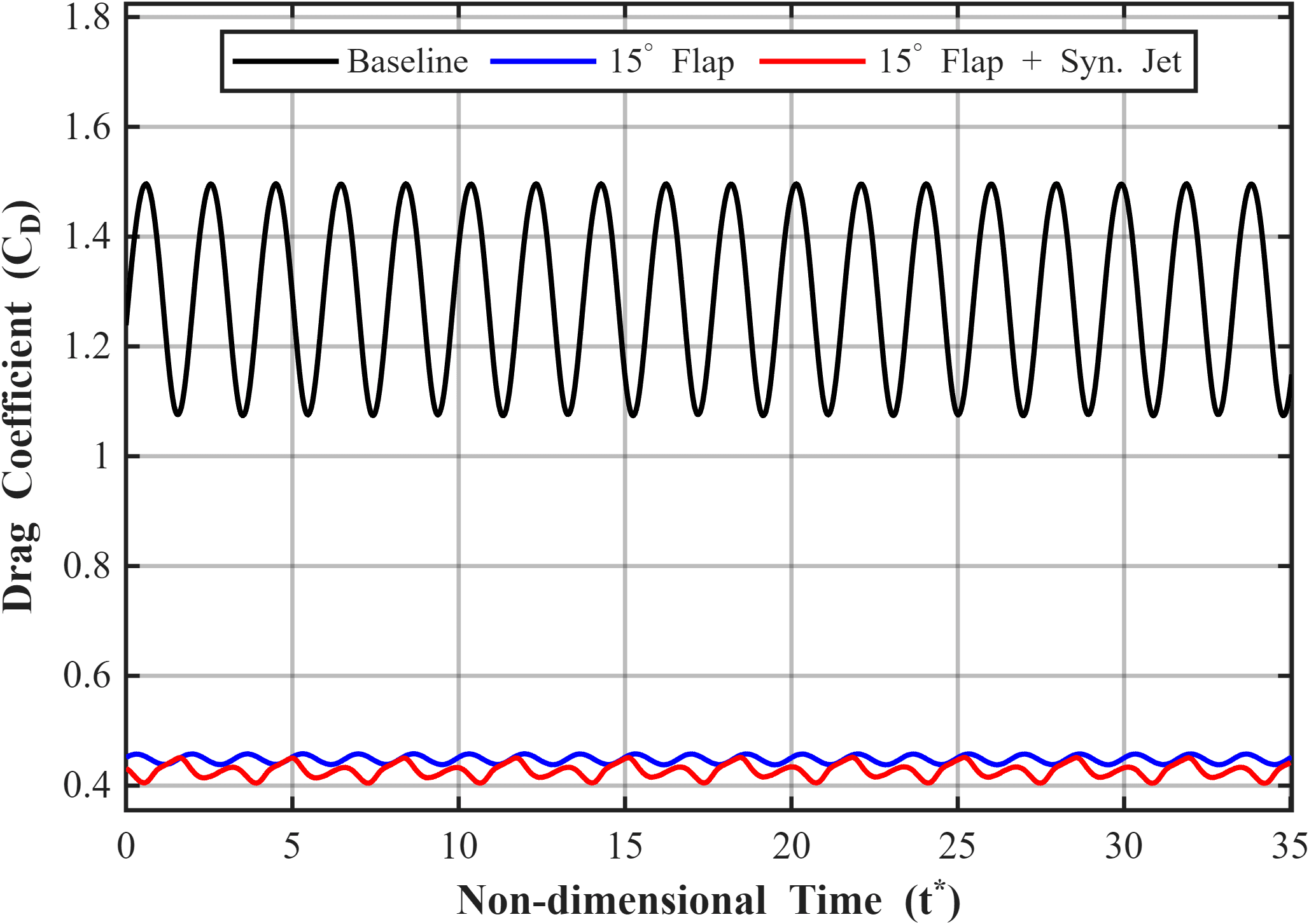
The baseline's large, sinusoidal lift and drag oscillations come from alternating vortex shedding off the sharp rear corners. Once the flap vectors the shear layers inward, both signals flatten and settle far closer to a steady state — the synthetic jet then breaks the remaining symmetry further, trading a small increase in RMS lift for additional pressure recovery at the base.
| Configuration | Mean C_D | RMS C_L | Base C_p |
|---|---|---|---|
| Baseline | 1.297 | 0.845 | -1.128 |
| 15° Flap | 0.448 | 0.166 | -0.343 |
| Flap + Synthetic Jet | 0.422 | 0.202 | -0.308 |
The work, outside of the solver.
Simulation results only matter once they meet hardware. A look at the research and prototyping work behind Tensorflux, captured during an active build cycle.
Integrating active and passive flow control substantially improves aerodynamic performance over the baseline: a 15° flap alone vectors the shear layer inward for a 65% drag reduction, and a phase-shifted synthetic jet — tuned to the wake's own 13 Hz shedding frequency — pushes total drag reduction to 67.49% while recovering base pressure by up to 72%.
Attribution
This work is original research conducted in-house by the Tensorflux engineering team, and directly informs the aerodynamic decisions behind our airframes.
Tensorflux Research · ongoing internal study
Have a flow-separation problem of your own?
This is the kind of question our CFD consulting practice answers for clients — bring us your geometry.